

Ich habe mal versucht diese Informationen in den Wikiartikel einzubauen. Bitte mal prüfen und ergänzen (Foto vFL wäre gut)
Beiträge von Go4IT
-
-
Thanks for feedback, lucky man!

It means the PBL was still in place but refuses to work for some time?
I've thought the UCDS adaptor had 3 CAN interfaces, or at least could connect to any, but this seems to be wrong. As i readout the versions of my DAB module on the desk, i first tried to scan it connected to MM CAN, but UcDS didn't find it. Then i switched over to MS CAN, connected it also to this port and it works.
Independantly of this we could learn a lot about this processor, because it is build into to many devices, even the Bosch Travelpilots.
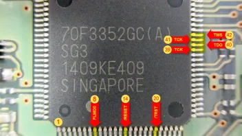
I've managed to solder very thin wires onto the unpopulatet JTAG pins of the micro, but had no time to test it. I'm going to do check this soon.
I wonder id it where possible to inject arbitrary code for the SBL, because this way it could be possible to write a downloader which reads the Flash and send its contents back to a CAN receiver. I know there is a checksum, but more to prevent against transportation errors than for security, though i even don't know how it's calculated. But maybe there is some sort of signature inside the binary which is checked by the PBL. Therefore it would be good to disassemble it's firmware...
-
Hab das gleiche Baujahr und hatte das gleiche Problem (siehe oben). Mir hat man gesagt, man habe den Sensor getauscht. Ob das stimmt kann ich natürlich nicht sagen. Meines Wissens nach hat der FL auch nicht diese massiven Kabelprobleme wie der vFL, was nicht heißt das es dennoch mal vorkommen kann.
-
As told in the docs, the V850ES did have an JTAG port for debugging and programming. It should be connected this way:
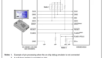
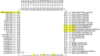
The signals are located on the yellow marked pins
It looks like the JTAG pins are not exposed to a connector pad on the board. Maybe the lanes are hidden by the chip itself, but there is a good chance it was not connected anywhere for security reasons. If so, it is more interesting for me, because they have something to hide
Look at the /TRST signal on the lower right. It is tied to GND by a resistor. This means the JTAG-Interface is always in reset-state an so disabled. A rising edge of that signal would enalbe it.
The /RESET Signal also does not seem to go anywhere.
So, what i could try next is to solder the JTAG-Signals to a Segger J-Link cable, remove the resistor blocking the TRST signal and look what i can find on the JTAG port. Then i am maybe empowerd to use this as seen in the specs of the chip: "Dynamic memory modification function (DMM function): RAM contents can be rewritten during program execution." With it, it should be possible to halt the CPU, replace the RAM content with the SBL code, set PC (Program counter) to the start address of it, and release the CPU. This way it may be possible to send the Firmware via CAN.
The signals FLMD0 and FLMD1 are used to set the powerup mode. FLMD1 is legally tied to GND by a resistor. FLMD0 should be high to put the chip into application mode (default). If it is set to low, the chip is in Flash programming mode. Thus is may be possible to erase and overwrite the Flash contents. But only, if the security bits are not set (which i assume they will be).
I've orded an 70F3352 from U.K. (funny, eh?) for about 20,- € just to proof my theory of flashing a virgin chip.
One of the ways should lead to success...
P.S.: Still looking for a guy who is able to disassemble the SBL or Firmware in order to find the 10 Byte security-ID of the chip
-
Beim einschalten müsste ja ein Kalibrierlauf kommen (einmal rauf runter).
Ergänzend zu dem was BBG-AE185 sagt ist noch zu erwähnen das die Höhenverstellung elektrisch auf beide Scheinwerfer parallel wirkt. D.H. da kommt nur ein Motorsignal aus dem Steuergärt (HCM). Daher reicht es sicher wenn einer nicht geht, das eine Störung erkannt wird und dafür sorgt das auch der andere stehen bleibt.
Du könntest einfach mal testen was er macht, wenn Du von einem Scheini der Stecker abziehst und dann einschaltest. So lässt sich die Fehlerquelle vielleicht eingrenzen. Einzig gehen die Scheinwerferstecker etwas schwer runter...
-
Also bei mir war der mal defekt und wurde damals noch im Rahmen der A1 Anschlußgarantie getauscht. Kann also durchaus sein das der Sensor defekt ist.
Bei mir hat er, im Sommer sehr hohe Temperaturen angezeigt, irgendwie 10-15 Grad über der tatsächlichen.
Der beste Test, steht auch im Wiki, wäre einen 2,5 kOhm Widerstand (Farbcode Rot/Grün/Rot) an die Pins von Stecker anzustecken und zu schauen ob er ca. 15 Grad anzeigt.
-

Das Hauptproblem bei den Updates ist, das man die oft nicht ohne weiteres wieder zurückrollen kann. Hier knausern die Hersteller bei den Chips oder den externen Flashes in den Modulen. Mit einem doppelt so großen Speicher (und hej, wir reden hier meist über ein paar MB bis zu 64MB, also wirklich nix wildes) könnte man einfach die alte Version vorhalten und mit einer einfachen Umschaltoption aktivieren. Somit wären auchgescheitere Modulupdates kein Todesurteil mehr. Aber ich denke vermutlich wieder mal viel zu Lösungsorientiert und nicht profitgierig genug...
-
I see. The PBL (Primary Boot Loader) is part of the binary image inside the file "CS7T-14D403-AJ.vbf".
The reason why it is so slow in progress of programming is because it needs to be done in small pieces (read my explaination above). My best guess for the reason it stuck is, that you tried to programm it over MS-CAN instead of using MM-CAN directly. Thus, the data must pass the IPC, which is the gateway from MS to MM, and maybe the IPC shuts down or filters some communication on the MM-CAN. So like you said, if one is goind to update a module on a CAN-Bus he should always connect to the bus the module is connected to. The other part is that it must be broke on a very unlucky moment, because the PBL is first swapped into a other memory location and overwritter as last, so an aborted self-programming could destroy the firmware but not the bootloader. So i think it was the very last step right before the update is finished, where it get lost.
Bringing the firmware back onto the chip is some kinde of "chicken/egg" problem. Please understand that my willingness to experiment with my working DAB module is not that big... so i won't test if the Flash could be erased and overwritten (the only chance i see to get it via JTAG). If you are willing to do, please go and tell if it works
You could also send me the faulty board and i try it, if you are not in charge of the necessary equipment to do.It may be an alternative to buy an virgin uPD70F3352 and replace it on the board. This chip could then be initially programmed with the firmware. This should do. Shure it would lock itself on the first run of the firmware, but that's ok as long as it works. Maybe i'm going to check this. uPDs are around 20€ or so. It's worth a try. If it works, i could program you a chip and send it to you so you could swap it yourself.
-
So, just connected my UCDS and DAB on my desk-CAN and here are the datas:
Module: DABM - Digital Audio Broadcast Module
Module-DID: F188
ECU Adresse: 0x7D6
CAN-Bus: MM-CAN
Teilenummer: CS7T-19C128-AG
Software-Release: CS7T-14D403-AH
Letzte Version: CS7T-14D403-AJ
Datei: CS7T-14D405-AA.vbf
Enthält: SBL (Secondary Bootloader): CS7T-14D405-AA
Description: This is the flash driver (SBL) for V850 microcontrollers with MF2 flash."
Call address on target: 0xFFFF 0000
Length: 0x0000 0A0C (= 2.572 Bytes)
Datei: CS7T-14D403-AJ.vbf
Enthält: Firmware: CS7T-14D403-AJ
Erase flash: Start=0x0000 6000, Length = 0x000B A000
Call address on target: 0x0000 6000
Length: 0x000B A000 (= 761.856 Bytes)
Now, surpise surpise! the program for the module is exactly the same size as the Flash of the V850 (70F3336)
 I extracted the BIN-portion of it (very easy, just use VBF-Extractor tool or my infos documented here: https://mk4-wiki.denkdose.de/artikel/vbf/start) and it is not fully used. From offset 0x31FA4 on there are only 0xFF in the bin-file, so the effective software is just 0x31FA4 Bytes long (decimal 204.708 Bytes). The padding bytes are just to ensure there is not "other" software residing in it, which can be called.
More interesting as the firmware itself is the SBL (secondary bootloader). It is very small, so it can fit into the MCUs RAM. There is gain access over the chip and do all necessary things like erasing the flash, loading the firmware data bytes over CAN, programming it into the flash and at least, starting it.
The firmware gets loaded at memory address 0x6000, which is common, because MCUs work memory-mapped. That means that periphals and other registers are mapped to "virtual" memory address locations. The Flash seems to start at 0x6000.
The SBL only gets loaded and executed, if the FBL (First bootloader) is in place, which does not seem true in your case. Because if, you should have had it reprogrammed with "Dead module programming" mode of UCDS.
-
was bringt das update?
Keine Ahnung, ich kenne zumindest keine Releasenote die darüber etwas aussagt. Qber das ein oder andere "Problemchen" taucht ja schonmal auf.
-

Na ja es ist ja so: Wenn keiner der in der Liste genannten Punkte zutrifft dann hat das Update ja keinen Sinn mehr, für was sollte man es also durchführen

Hinweis an Go4IT:
Der Titel hier stimmt nicht ganz, das Update 5.3 ist ja fürs NX
Ups, danke für den Hinweis Dermon4 ! Habs geändert, leider ändert sich dadurch auch der Link:
-
Es ist halt leider wie immer: Entweder etwas Risiko und Eigeninitiative, oder aber auf Nummer Sicher gehen und alles vom Händler besorgen und von Fachfirma einbauen lassen. Das liegt jetzt etwas an Dir, was Du dir zutraust und wie bereit Du bist Zeit und Geld zu investieren...
-
Hey, would you please send me the ZIP of the downloaded firmware package for the Module?
I could do myself, but too less time
Then i look inside, let's see what we find.
-
Du benötigst ein Sound&Connect Modul mit USB. Damit dieses bei dir funktioniert, muss der Kabelbaum angepasst werden. Alles hier im Forum beschrieben. Dann noch freischalten und fertig.
Das NX muss auf jeden Fall upgedated werden, sonst wird das nicht klappen. Ne nach Kartenmaterial muss er dann auch noch neue Navi-Karten haben. Zumindest sollte der Stand >= 2012 sein.
Sein Convers+ (falls vorhanden) sollte er auch updaten, sonst kann er es dort nicht steuern. Naja, muss ja vielleicht auch nicht
-
I gues the manufacturers protect their IP ("intellectual propert", or just call it Software) as good as they can. Especially those Renasas chips are made for automation devices and widely used. If they are known to be hacked easily by every script kiddie the industry would have moved to other devices. So it will not be easy to do what we are thinking about.
You can read of the possibilities for securing the chip against readout or overwrite i this document of the V850 series: https://www.renesas.com/eu/en/doc/prod…1eu0101_mcu.pdf
As you read you find that it is not a big deal to safe the chip from beeing "debugged", read out flash or erase and overwrite flash by some simple flags on initial programming. Some of the functions could be activatet by providing a 10 Byte long password on the initial sequence to connect, using a E1 Emulator or any other tool. This is nearly impossible to hack, you need to know it from "somewhere" ;.)
The program, the chip is executing, comes directly from the Flash. The RAM is only used for variable data. This is, like most MCU do it, e.g. the well known Atmega or STM32 chips.
The mode of "self-programming" which is used to update the module by software, as you do it on CAN updating, is special and may be the only backdoor. The V850 has very limited RAM, only 60 kb. What it does is, when there is a CAN update procedure initialized, it will copy and start a little piece of software from the Flash into the RAM. This small tool has only one job: erase the internal flash (maybe block by block), read a small portion of the firmware to be programmed from the CAN (only a few messages at once) because it has only a handfull of kilobytes left in RAM to store it, and program that piece/block into the Flash. If all is done, it resets itself and the new Firmware is in place. This is also the reason why some module updates seem to be incredicble slow (e.g. the bluetooth module).
The reason why some programmings fails are that the modul restarts before this process is finished. Or the dataflow stops or is too slow. This little self-programming software has not enough memory to do error correction or retransmits or any anything. This is why your friends update bricks the device.
Now, what hackers may do is to try to inject some own software into the RAM of the MCU, which is able to do the self-programming, like the genuine software does. But because the chip does not boot or not have this software in place , because of the broken update, it can't reach this status itself. So one must know how to do the programming. Maybe by reading the firmware over the UART port of the chip, instead of the CAN, because serial lines need much less overhead and program code than CAN communication. Maybe the same principle could be used to read the Flash content and send it via UART or JTAG port.
The challenge now is to find a tool which can do this. There are "car programmers" available, which claims to read V850 flash. But they are expensive...
P.S.: Braucht jemand hiervon eine deutsche Übersetzung?
-
The DAB Module is driven from an V850 microcontroller (70F3352) which has very limited ressources. Only 768 kb of internal Flash and there is no external Flash or EEPROM on the board. https://mk4-wiki.denkdose.de/artikel/dab/dab_teardown
The V850 do have JTAG to program and debug, but usually is protected against readout. Maybe it's not only protected against reads but also lock itself down on trying to do so. I had similar problems with an equal chip on a Convers board.
But what should be possible is to overwrite the internal Flash with new content. But therefore you need the content. It should be inside the vbf you downloaded via UCDS, but needs to be extracted.
-
Warum müssen wir eigentlich immer über Dinge rätseln die der TE mit einem kleinen Satz klären könnte? Haben wir hier alle nix zu tun? Manchmal finde ich es befremdlich. Überhaupt scheint der TE kein besonderes Interesse an den Antworten zu haben zumindest kommt ja nix von ihm...
-
Uuuh, stimmt!

Da muss ich mich erst dran gewöhnen das hier nun auch MK5ler ihr Unwesen treiben
-
So, hier hätte ich dann schonmal das Pinout für den Verstärker:
https://mk4-wiki.denkdose.de/artikel/audio_…sound_amplifier
Laut Schaltplan werden in den vorderen Türen die Tief- und Hochtöner separat versorgt, hinten bleibt alles gleich. Auch ist da zu erkennen das neben dem Subwoofer auch der Center von der Endstufe kommt. Dieser wird aber NF-Audioseitig nicht eingespeist, sondern nur die 4 Lautsprecherausgänge. Tja, jetzt ist die Frage wie es besser ist, denn das MCA2 hat ja einen eigenen Center-Verstärker und man kann ihn direkt am Radio anschließen. Von den "Innereien" des Poweramp ist der gut in der Lage die Signale selbst zu generieren. Darauf werkelt, unter anderem, ein eigener DSP (AD1940). In beiden Fällen gibt es ja keine wirkliche Center-Quelle, sprich das ist ja ein Stereo-Signal und kein 5.1 oder AC3 oder sowas.
Jetzt werde ich mal überprüfen was der Amp und das Radio per CAN so miteinander quatschen und ob sich an den Lautsprecherausgängen vom Radio pegelmäßig was ändert wenn der Amp mit im Netz ist.
-