First of all, this will be a journey, not a quick trip, so prepare to spend a lot of time for this to fix. It's perfect to have an alternative meanwhile, as you will by adding a separate climate control unit. Hope you electronic skills are high and also your equipment. You should be familiar with SMD soldering/desoldering and should have a digital oscilloscope, measurement equipment and an adjustable power source.
To power the unit you just need to apply 12V (~1.8 - 2.0A) to the pins 12 (GND) and 15 (+) of the Quadlock, that's enough: https://mk4-wiki.denkdose.de/artikel/ audio_navigation/quadlock#supply
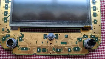
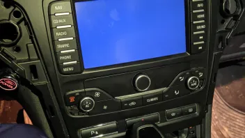
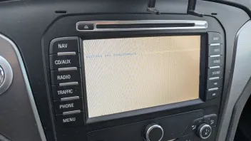
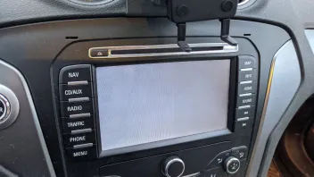
The "white" you see is due to the background illumination of the display. Normally the crystals inside the LCD screen are aligned to shade the light from it and/or form color filters to only pass color components of a specific amount. This way the pixels turns black/white or any color between. Such LCDs needs a lot of different voltage to work. They are derived from this converter.
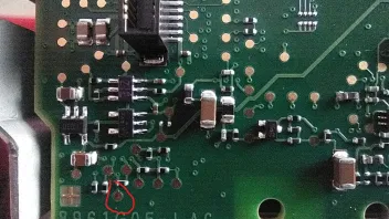
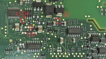
You should always measure to GND:
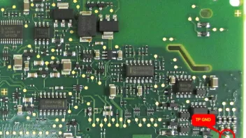
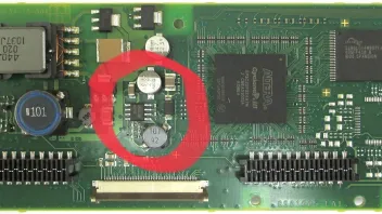
The 5V you measure is the input power of the boost converter MC34063 (the chip in the middle of the red circle). It shows that the converter is getting the needed input power to work, good!
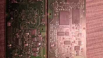
The "LCD+" should be the output voltage the converter produces. In my writings it was about +12V (which fits your measuring). The "LCD-" should produce negative voltage, -8.3V.
Check the rectifier diodes (BAV99, SOT-23 case) as they might reported (use a simple DMM for it):
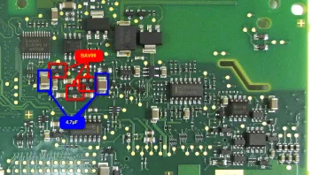
Also check the caps at least measure resistance if not capacity. The should not have a resistance, if they have, they are melted.