DAB module dead after update

  • Hey a friend updated his DAB module with ucds and it has bricked his module

    Is there any way to repair this

    For example Could you read the flash from a working module with some tools and write it to the bricked module

    Go4it your a very good tech wizard any thoughts?

  • The DAB Module is driven from an V850 microcontroller (70F3352) which has very limited ressources. Only 768 kb of internal Flash and there is no external Flash or EEPROM on the board. https://mk4-wiki.denkdose.de/artikel/dab/dab_teardown

    The V850 do have JTAG to program and debug, but usually is protected against readout. Maybe it's not only protected against reads but also lock itself down on trying to do so. I had similar problems with an equal chip on a Convers board.

    But what should be possible is to overwrite the internal Flash with new content. But therefore you need the content. It should be inside the vbf you downloaded via UCDS, but needs to be extracted.

    "Lernen ist Erfahrung. Alles andere ist einfach nur Information."

    Albert Einstein

  • Thanks for your reply, how would we go about extracting the needed data and what would we need to write this too the microcontroller

  • I gues the manufacturers protect their IP ("intellectual propert", or just call it Software) as good as they can. Especially those Renasas chips are made for automation devices and widely used. If they are known to be hacked easily by every script kiddie the industry would have moved to other devices. So it will not be easy to do what we are thinking about.

    You can read of the possibilities for securing the chip against readout or overwrite i this document of the V850 series: https://www.renesas.com/eu/en/doc/prod…1eu0101_mcu.pdf

    As you read you find that it is not a big deal to safe the chip from beeing "debugged", read out flash or erase and overwrite flash by some simple flags on initial programming. Some of the functions could be activatet by providing a 10 Byte long password on the initial sequence to connect, using a E1 Emulator or any other tool. This is nearly impossible to hack, you need to know it from "somewhere" ;.)

    The program, the chip is executing, comes directly from the Flash. The RAM is only used for variable data. This is, like most MCU do it, e.g. the well known Atmega or STM32 chips.

    The mode of "self-programming" which is used to update the module by software, as you do it on CAN updating, is special and may be the only backdoor. The V850 has very limited RAM, only 60 kb. What it does is, when there is a CAN update procedure initialized, it will copy and start a little piece of software from the Flash into the RAM. This small tool has only one job: erase the internal flash (maybe block by block), read a small portion of the firmware to be programmed from the CAN (only a few messages at once) because it has only a handfull of kilobytes left in RAM to store it, and program that piece/block into the Flash. If all is done, it resets itself and the new Firmware is in place. This is also the reason why some module updates seem to be incredicble slow (e.g. the bluetooth module).

    The reason why some programmings fails are that the modul restarts before this process is finished. Or the dataflow stops or is too slow. This little self-programming software has not enough memory to do error correction or retransmits or any anything. This is why your friends update bricks the device.

    Now, what hackers may do is to try to inject some own software into the RAM of the MCU, which is able to do the self-programming, like the genuine software does. But because the chip does not boot or not have this software in place , because of the broken update, it can't reach this status itself. So one must know how to do the programming. Maybe by reading the firmware over the UART port of the chip, instead of the CAN, because serial lines need much less overhead and program code than CAN communication. Maybe the same principle could be used to read the Flash content and send it via UART or JTAG port.

    The challenge now is to find a tool which can do this. There are "car programmers" available, which claims to read V850 flash. But they are expensive...

    P.S.: Braucht jemand hiervon eine deutsche Übersetzung?

    "Lernen ist Erfahrung. Alles andere ist einfach nur Information."

    Albert Einstein

    Einmal editiert, zuletzt von Go4IT (27. Januar 2019 um 13:27)

  • Hey, would you please send me the ZIP of the downloaded firmware package for the Module?

    I could do myself, but too less time ;)

    Then i look inside, let's see what we find.

    "Lernen ist Erfahrung. Alles andere ist einfach nur Information."

    Albert Einstein

  • was bringt das update?

    Mondeo 1993 CLX 16V 90PS
    Mondeo 2008 Titanium X 2.5T 270PS
    Mondeo 2010 2.0T Titanium S 240PS

  • was bringt das update?

    Keine Ahnung, ich kenne zumindest keine Releasenote die darüber etwas aussagt. Qber das ein oder andere "Problemchen" taucht ja schonmal auf.

    "Lernen ist Erfahrung. Alles andere ist einfach nur Information."

    Albert Einstein

  • So, just connected my UCDS and DAB on my desk-CAN and here are the datas:

    Module: DABM - Digital Audio Broadcast Module

    Module-DID: F188

    ECU Adresse: 0x7D6

    CAN-Bus: MM-CAN

    Teilenummer: CS7T-19C128-AG

    Software-Release: CS7T-14D403-AH

    Letzte Version: CS7T-14D403-AJ

    Datei: CS7T-14D405-AA.vbf

    Enthält: SBL (Secondary Bootloader): CS7T-14D405-AA

    Description: This is the flash driver (SBL) for V850 microcontrollers with MF2 flash."

    Call address on target: 0xFFFF 0000

    Length: 0x0000 0A0C (= 2.572 Bytes)

    Datei: CS7T-14D403-AJ.vbf

    Enthält: Firmware: CS7T-14D403-AJ

    Erase flash: Start=0x0000 6000, Length = 0x000B A000

    Call address on target: 0x0000 6000

    Length: 0x000B A000 (= 761.856 Bytes)

    Now, surpise surpise! the program for the module is exactly the same size as the Flash of the V850 (70F3336) ;) I extracted the BIN-portion of it (very easy, just use VBF-Extractor tool or my infos documented here: https://mk4-wiki.denkdose.de/artikel/vbf/start) and it is not fully used. From offset 0x31FA4 on there are only 0xFF in the bin-file, so the effective software is just 0x31FA4 Bytes long (decimal 204.708 Bytes). The padding bytes are just to ensure there is not "other" software residing in it, which can be called.

    More interesting as the firmware itself is the SBL (secondary bootloader). It is very small, so it can fit into the MCUs RAM. There is gain access over the chip and do all necessary things like erasing the flash, loading the firmware data bytes over CAN, programming it into the flash and at least, starting it.

    The firmware gets loaded at memory address 0x6000, which is common, because MCUs work memory-mapped. That means that periphals and other registers are mapped to "virtual" memory address locations. The Flash seems to start at 0x6000.

    The SBL only gets loaded and executed, if the FBL (First bootloader) is in place, which does not seem true in your case. Because if, you should have had it reprogrammed with "Dead module programming" mode of UCDS.

    "Lernen ist Erfahrung. Alles andere ist einfach nur Information."

    Albert Einstein

  • So - I am the friend who managed to brick the DAB module!

    I tried using UCDS and Upgrade Wizard to update DABM from AF to AH - it erased successfully and started flashing VERY slowly. got to 20% and failed.

    Subsequent attempts have failed and DAB module is not even detected in module scan now. i have tried force flash through upgrade wizard, and by loading the SBL and update files into the VBF loader to force program, each time is reports back that force Programming request failed.

    I think my mistake at the start (apart from updating the module!) is that i did not select to flash via MM-CAN - and when you load the vbf files into vbf loader in UCDS it reports that they operate on the MS-CAN bus, not the MM-CAN bus - something that entered my mind when it was crawling through the flash process! I have since tried to flash in forced MM-CAN mode and through normal MS-CAN mode, but with no success. interestingly when i attempted a forced flash without selecting MM-CAN, i got a DTC from the ACM simply saying "MS-Can bus" - which cleared and didn't come back.

    So...it seems you are correct, the FBL is not in place and therefore i cannot get the SBL to load to try and get the software back on there. So the next question is - is there a way to push the Primary bootloader back onto it?

  • I see. The PBL (Primary Boot Loader) is part of the binary image inside the file "CS7T-14D403-AJ.vbf".

    The reason why it is so slow in progress of programming is because it needs to be done in small pieces (read my explaination above). My best guess for the reason it stuck is, that you tried to programm it over MS-CAN instead of using MM-CAN directly. Thus, the data must pass the IPC, which is the gateway from MS to MM, and maybe the IPC shuts down or filters some communication on the MM-CAN. So like you said, if one is goind to update a module on a CAN-Bus he should always connect to the bus the module is connected to. The other part is that it must be broke on a very unlucky moment, because the PBL is first swapped into a other memory location and overwritter as last, so an aborted self-programming could destroy the firmware but not the bootloader. So i think it was the very last step right before the update is finished, where it get lost.

    Bringing the firmware back onto the chip is some kinde of "chicken/egg" problem. Please understand that my willingness to experiment with my working DAB module is not that big... so i won't test if the Flash could be erased and overwritten (the only chance i see to get it via JTAG). If you are willing to do, please go and tell if it works :) You could also send me the faulty board and i try it, if you are not in charge of the necessary equipment to do.

    It may be an alternative to buy an virgin uPD70F3352 and replace it on the board. This chip could then be initially programmed with the firmware. This should do. Shure it would lock itself on the first run of the firmware, but that's ok as long as it works. Maybe i'm going to check this. uPDs are around 20€ or so. It's worth a try. If it works, i could program you a chip and send it to you so you could swap it yourself.

    "Lernen ist Erfahrung. Alles andere ist einfach nur Information."

    Albert Einstein

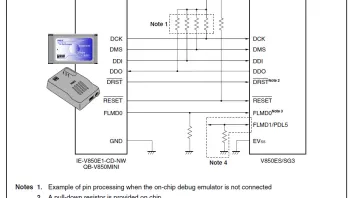
  • As told in the docs, the V850ES did have an JTAG port for debugging and programming. It should be connected this way:

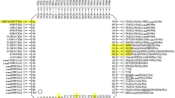
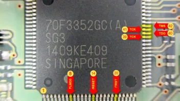
    The signals are located on the yellow marked pins

    It looks like the JTAG pins are not exposed to a connector pad on the board. Maybe the lanes are hidden by the chip itself, but there is a good chance it was not connected anywhere for security reasons. If so, it is more interesting for me, because they have something to hide :)

    Look at the /TRST signal on the lower right. It is tied to GND by a resistor. This means the JTAG-Interface is always in reset-state an so disabled. A rising edge of that signal would enalbe it.

    The /RESET Signal also does not seem to go anywhere.

    So, what i could try next is to solder the JTAG-Signals to a Segger J-Link cable, remove the resistor blocking the TRST signal and look what i can find on the JTAG port. Then i am maybe empowerd to use this as seen in the specs of the chip: "Dynamic memory modification function (DMM function): RAM contents can be rewritten during program execution." With it, it should be possible to halt the CPU, replace the RAM content with the SBL code, set PC (Program counter) to the start address of it, and release the CPU. This way it may be possible to send the Firmware via CAN.

    The signals FLMD0 and FLMD1 are used to set the powerup mode. FLMD1 is legally tied to GND by a resistor. FLMD0 should be high to put the chip into application mode (default). If it is set to low, the chip is in Flash programming mode. Thus is may be possible to erase and overwrite the Flash contents. But only, if the security bits are not set (which i assume they will be).

    I've orded an 70F3352 from U.K. (funny, eh?) for about 20,- € just to proof my theory of flashing a virgin chip.

    One of the ways should lead to success...

    P.S.: Still looking for a guy who is able to disassemble the SBL or Firmware in order to find the 10 Byte security-ID of the chip :)

    "Lernen ist Erfahrung. Alles andere ist einfach nur Information."

    Albert Einstein

  • very intresting stuff there go4it, how did you learn all this stuff

  • thats is incredibly interesting info go4fit - wish i knew half of what you do....!

    I've had an interesting evening myself - after speaking to Alexey (Conversmod), he suggested a direct connection to MM-CAN on UCDS adapter and power the module on the bench to try force flash - and be patient as timing is everything.

    With this in mind i tried about 20-30 times, forcing through MM-CAN - ws just about to give up when it suddenly caught and the SBL loaded. interestingly, it flashed the module and verified it in under a minute.

    Now installed and working again :)

  • Thanks for feedback, lucky man! :)

    It means the PBL was still in place but refuses to work for some time?

    I've thought the UCDS adaptor had 3 CAN interfaces, or at least could connect to any, but this seems to be wrong. As i readout the versions of my DAB module on the desk, i first tried to scan it connected to MM CAN, but UcDS didn't find it. Then i switched over to MS CAN, connected it also to this port and it works.

    Independantly of this we could learn a lot about this processor, because it is build into to many devices, even the Bosch Travelpilots.

    I've managed to solder very thin wires onto the unpopulatet JTAG pins of the micro, but had no time to test it. I'm going to do check this soon.

    I wonder id it where possible to inject arbitrary code for the SBL, because this way it could be possible to write a downloader which reads the Flash and send its contents back to a CAN receiver. I know there is a checksum, but more to prevent against transportation errors than for security, though i even don't know how it's calculated. But maybe there is some sort of signature inside the binary which is checked by the PBL. Therefore it would be good to disassemble it's firmware...

    "Lernen ist Erfahrung. Alles andere ist einfach nur Information."

    Albert Einstein

  • The UCDS adapter does have three interfaces from what I have been told:

    HS-CAN: 6 & 14

    MS-CAN: 3 & 11

    MM-CAN: 1 & 8

    I was connected to MS-CAN, with a 120R resistor across High and Low and repeated attempts forcing MM-CAN failed to get a response. I am not 100% sure that i rememebered to select MM-CAN in upgrade wizard the last time it worked!

    From other info I have been told, it does not matter which bus pins you are connected to on the bench MS or MM because apparently the Mk4 has 125kbit bus speed on both; UCDS is told what speed to use when you select the car type. - so technically it should work on either bus.

  • What are you trying to tell us?

    "Lernen ist Erfahrung. Alles andere ist einfach nur Information."

    Albert Einstein

Jetzt mitmachen!

Sie haben noch kein Benutzerkonto auf unserer Seite? Registrieren Sie sich kostenlos und nehmen Sie an unserer Community teil!